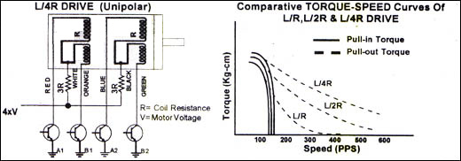
D. C. STEPPING MOTOR


Stepping motor is an electromagnetic device which converts digital pulses into discrete mechanical rotational movements. The motors are hybrid type unipolar or bipolar having   multi- toothed   rotor & stator. The rotor uses permanent magnet & the stator is two phase pair (four phase)   bifilar winding, with 6 leads or 8 leads.


 GENERAL SPECIFICATIONS :
 
Type                            : Hybrid Type; Unipolar or Bipolar
Phase : Two phase pair (four phase)
Step Angles                  : 1.8° full step; 0.9° half step
Angular Accuracy           : ± 5% non-cumulative (No load)
Swithching Sequence     : 4 step (Full step); 8 step (Half step)
Stator winding               : Bifiliar, 6 leads or optional 8 leads
Operating Temp           : -10° C to 50° C
Temp Rise                     : Max 80° C
Insulation Class    : Class B
Insulation Resistance      : 100 MΩ min. at 500 V.D.C.
Dielectric Strength : 500V A.C. for 1 Minute
Holding Torque         : 2 to 60 kg-cm in 12 models
Frame size (O.D.)  : 58 mm, 86 mm & 108 mm
     

 STEPPING MOTOR WORKING :
 

The stepping action of motor shaft is caused by sequential switching of supply   to   the two phase pair of motor as shown in full step & half step logic sequence table. Motor direction can be  changed either by reversing logic   sequence direction or by interchanging connection of any one phase pair.


  SPECIAL FEATURES :
 

1)

A wide range of rotating speeds (stepping rate) proportional to the frequency of the pulse signal is


provided.

2)

The rotating angle of the motor is directly proportional to the number of input pulses.

3)

The angle error per step is very small & non-cumulative.

4)

Rapid response to starting / stopping & reversing.

5)

Digital input pulse signal provide open-loop control, thus making the system simple & avoiding the need

for closed loop system for less critical application.

6)

Self-holding capability makes it possible for the rotor to be held in the stepped position without the use

of  brakes.


  TERMINOLOGY :
     
  1) Torque-Speed curve


  2) Holding Torque : It is the maximum torque require to change the step angle, When the stator winding
    is in exciting state at the rated voltage.
     
  3) Detent Torque : Torque created on the output shaft of a motor, when stator is in no exciting state &
    whose rotor uses permanent magnet.
     
  4) Step Angle : The nominal angle through which the shaft of a stepping motor turns in response to one
    pulse signal.
     
  5) Start-Stop Region : The region, in which a stepping motor can start, stop or reverse in synchronism
    with the external pulse signal.
     
  6) Slew Range : In the region above the start-stop region, a stepping motor can respond without loss of
    synchronism, even when there is a gradual increase in the frequency or the torque load within this
    region.
     
  7) Pull-in Torque : The max. torque at which an energized stepping motor will start and run in
    synchronism in the start-stop region.
     
  8) Pull-out Torque : The max. torque which can be applied to the shaft of a stepping motor without loss
    of synchronism, even when there is a gradual increase in frequency or load torque within the slew
    range.
     
  9) Resonance : When a motor is operated at its natural frequency, typically 90 to 180 pps or sometimes
    in the higher frequency region, suddenly an increase in the audio and vibration depending on motor 
    model selected. In some cases motor will reverse or miss-step also.
     
  10) Acceleration and Deceleration (Ramping ) : In most cases, a stepping motor cannot achieve high
    speeds immediately when started and will overshoot if not decelerated from these speeds. Therefore,
    acceleration and deceleration, or "ramping" as it is commonly known, must be provided to assure
    realiable stepping and maintain positioning accuracy in the slew range region.
 

 'VISHAL-SYN' D.C. STEPPING MOTOR MODELS & SPECIFICATIONS


Motor Model
Holding Torque
Detent Torque Kg-cm
Rotor Inertia  Gm-cm2
Current Amp./ Phase
O.D.
mm
Length
mm
Weight (app.) kg.
D.C. Voltage
1-Phase energised Kg-cm
2-Phase energised Kg-cm
6V
12V
24V
 STM-231SP
2
2.8
0.100
120
1.00
0.50
0.25

58

60
0.600
 STM-232
4
5.6
0.250
230
1.50
0.70
0.35
58 80
1.100
 STM-233
6
8.4
0.400
320
1.80
0.9
0.45
58 105
1.500
 STM-341
3.5
5.0
0.400
610
1.35
0.68
0.35
86 68
1.400
 STM-341SP
7
9.9
0.450
650
1.40
0.70
0.40
86 68
1.500
 STM-342
14
19.7
0.700
1280
2.50
1.20
0.60
86 120
3.100
 STM-343
21
29.8
0.800
1890
3.50
1.80
0.90
86 150
4.000
 STM-421
10
14.0
1.000
3200
3.30
1.50
0.65
108 80
3.100
 STM-421SP
20
28.0
1.600
3800
3.30
1.50
0.65
108 80
3.400
 STM-422SP
28
36.0
1.800
4000
3.30
1.50
0.67
108 85
3.700
 STM-422
40
56.0
3.100
7000
4.50
2.25
1.30
108 155
6.300
 STM-423
60
84.0
4.800
10800
6.00
3.00
----
108 215
10.500
 

Logic Sequence Table


Note: If extended motor shaft is required, add suffix 'E' in the motor model selected. e.g.:STM-341E etc.


Stepping Motor Model
Torque Kg-cm
Dimensions (mm)

Weight  Kg

A
B C D E F G ØH ØJ Øk
 STM-231SP
2
58
47.2
60
6
1.2
22
21
6.35
38
5
0.600
 STM-232
4
58
47.2
80
6
1.2
22
21
6.35
38
5
1.000
 STM-233
6
58
47.2
105
6
1.2
22
21
6.35
38
5
1.400
 STM-341
3.5
86
70
68
7
1.2
27
21
10
73
7
1.400
 STM-341SP
7
86
70
68
7
1.2
27
21
10
73
7
1.500
 STM-342
14
86
70
120
7
1.2
27
21
10
73
7
3.100
 STM-343
21
86
70
150
7
1.2
27
21
10
73
7
4.000
 STM-421
10
108
85
80
7
1.5
27
22
10
55
8
3.000
 STM-421SP
20
108
85
80
7
1.5
27
22
10
55
8
3.400
 STM-422SP
28
108
85
135
7
1.5
27
22
10
55
8
4.200
 STM-422
40
108
85
155
7
1.5
50
22
15
55
8
6.300
 STM-423
60

108

85 215 7 1.5 50 22 15 55 8 10.100
 

In view of the 'VISHAL' policy of continuous development & improvement the information in this leaflet is subject to change without notice.


Download Catalouge


A.C. Synchronous Motor, D.C. Stepping Motor, PDMC Geared Motor, Plastic Moulded Gears, Geared Synchronous/Stepper Motor.
@ 2006 Vishal Electromag Industries